
OpenWrt-One VLAN Setup
How to set up basic VLAN network segmentation on the single OpenWrt-One LAN interface via LuCI.
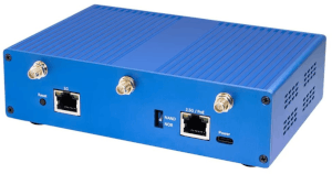
The OpenWrt One router board features only one physical interface for WAN and LAN each. A VLAN-capable managed switch is thus needed for L2 network segmentation. This guide documents how to use the LuCI frontend GUI to configure VLANs with their own /24 subnets via DHCP for interface- or address-based firewalling and routing.
Initial State
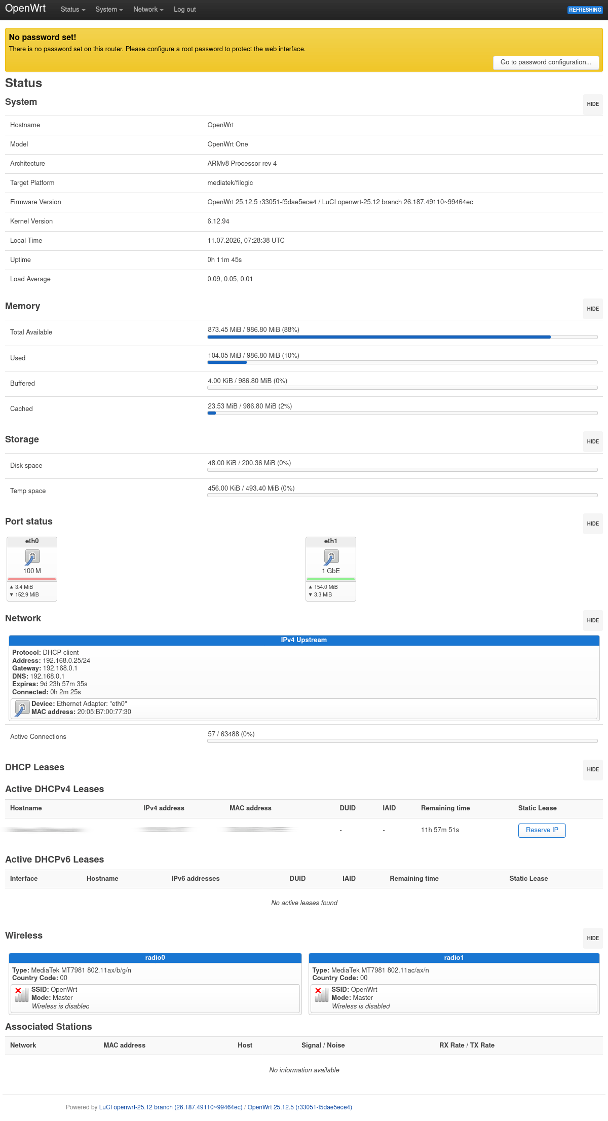
After first boot, the WAN port (2.5G) automatically acts as a DHCP client, while the LAN port (1G) functions as a DHCP server for the 192.168.1.1/24 subnet.
Firmware upgrades and other initial setup steps are not covered here. The first login as root with an empty password shows: (click for more details on what to expect)
Swap WAN/LAN Ports
The default assignment of 2.5G to WAN and 1G to LAN might make sense in the general case as the uplink needs to serve both LAN and WiFi. However, this allocation can be suboptimal if no >1G WAN downstream is to be expected, while upgrading the LAN-side is a more likely option. The first step is thus to swap the interfaces.
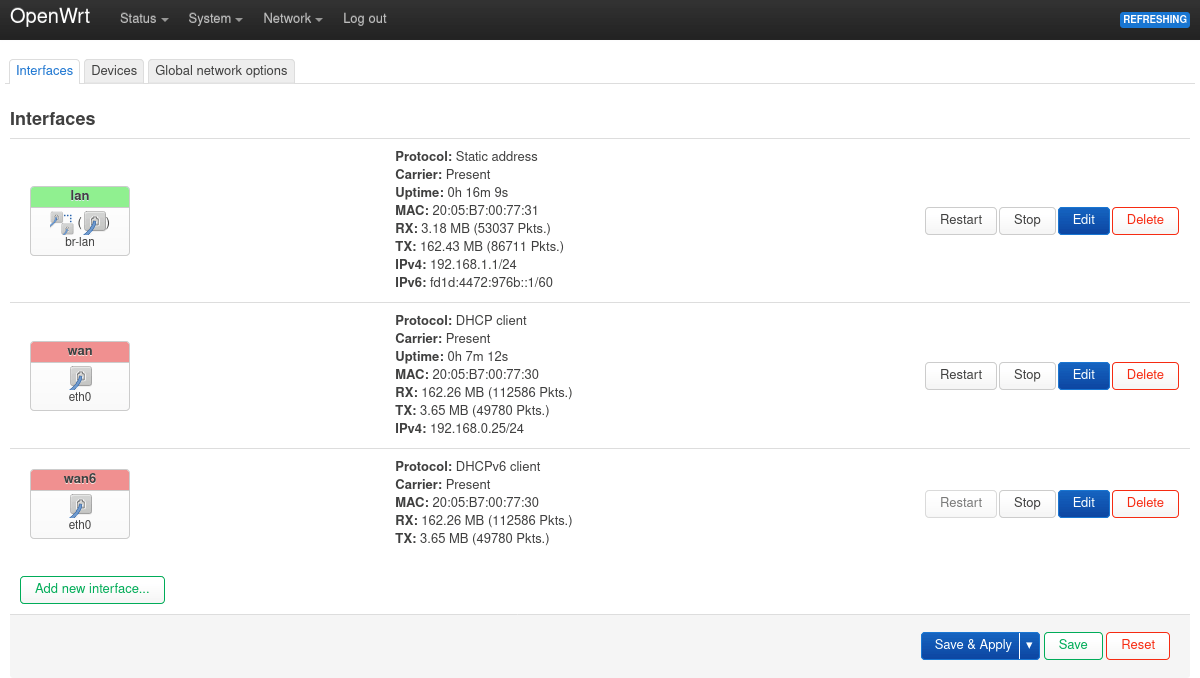
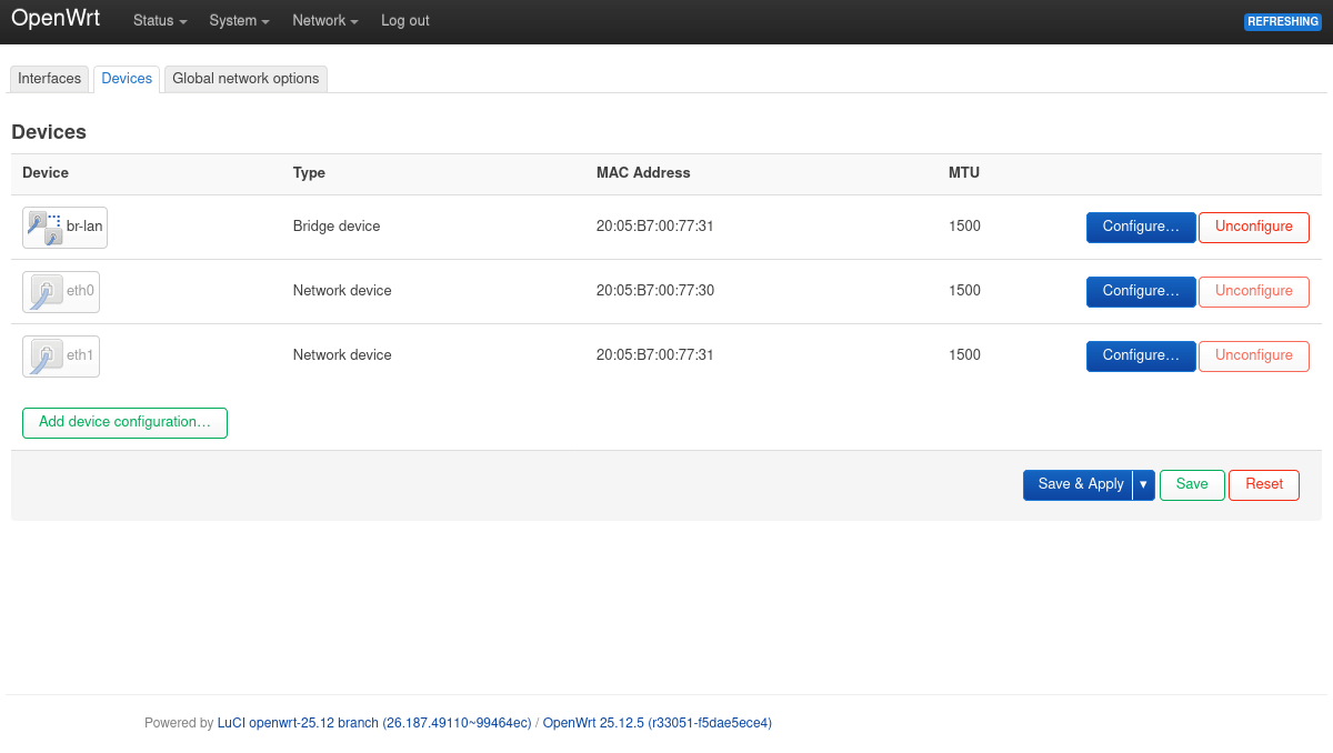
With one physical port only, using a bridge with “VLAN filtering” is not strictly needed – the interfaces can be referenced directly.
wan: change device frometh0toeth1lan: change device frombr-lantoeth0, the bridge is then unused and can be deleted
Note that after hitting Save & Apply, cables should be swapped promptly: The transaction might get rolled back if there’s no timely reconnect from the browser to the frontend.
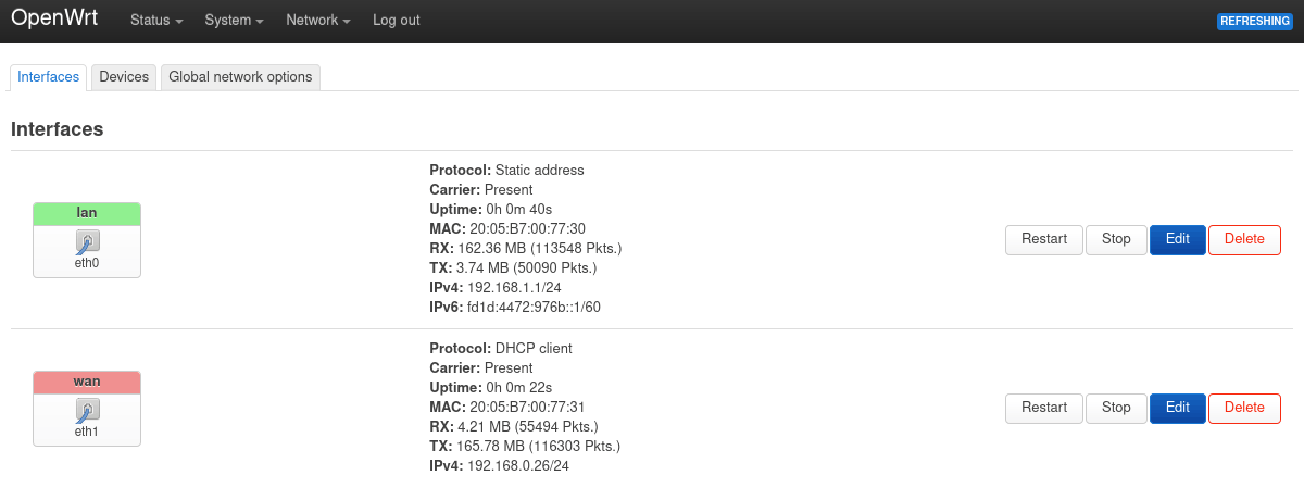
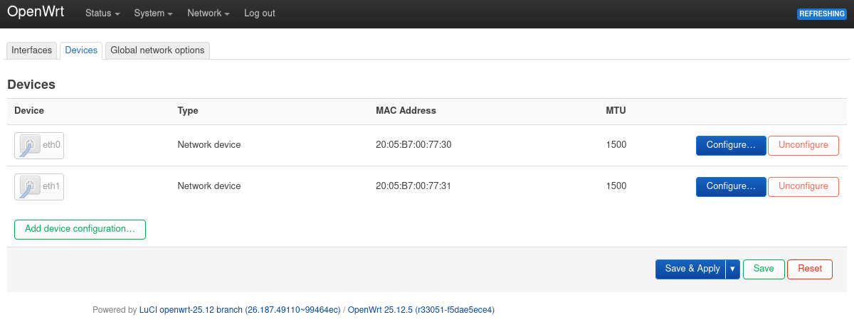
For this initial setup, the wan6 interface was deleted for now as well.
If desired, IPv6 can be disabled further via: network device configuration, RA settings for the DHCP server, filtering of AAAA records in the DNS server, and by removing the corresponding firewall rules.
Add VLAN Interfaces
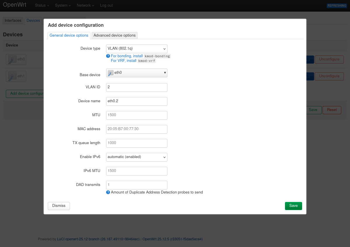
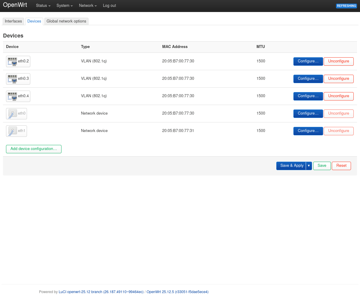
First, Add device configuration with device type “VLAN (802.1q)”, VLAN ID 2, and eth0 (LAN) as base device.
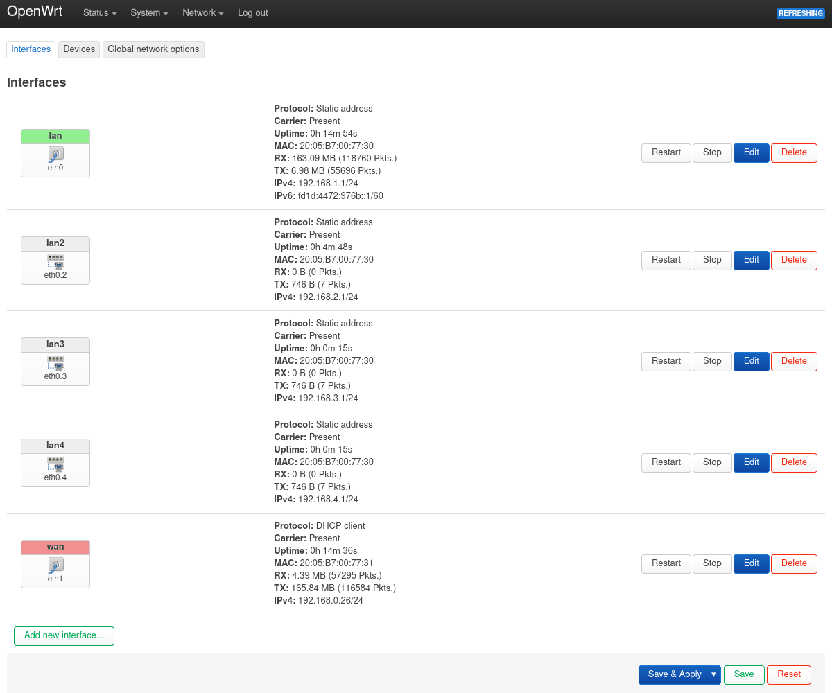
The resulting eth0.2 can then be used as device in Add new interface, while choosing a static address and enabling the DHCP server.
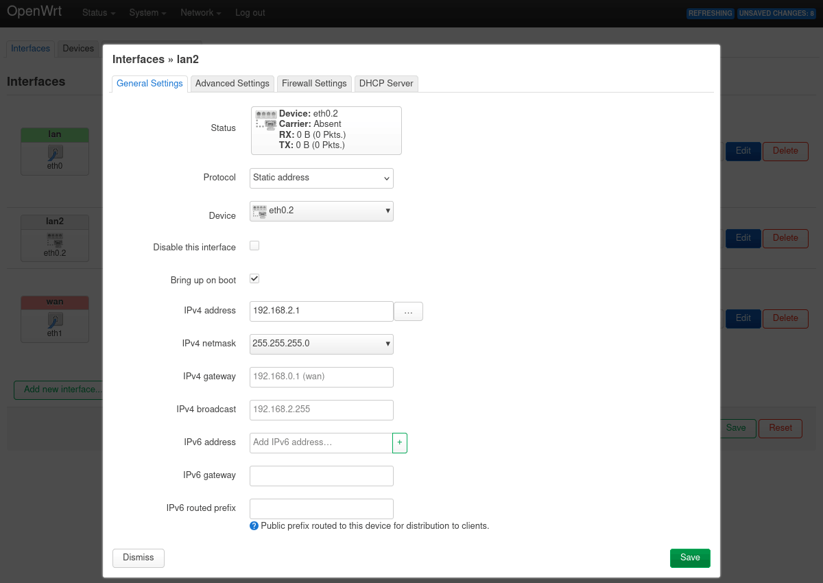
Repeating this process also for IDs 3/4 and clicking Save & Apply should produce the following configuration:
Basic Firewall Configuration
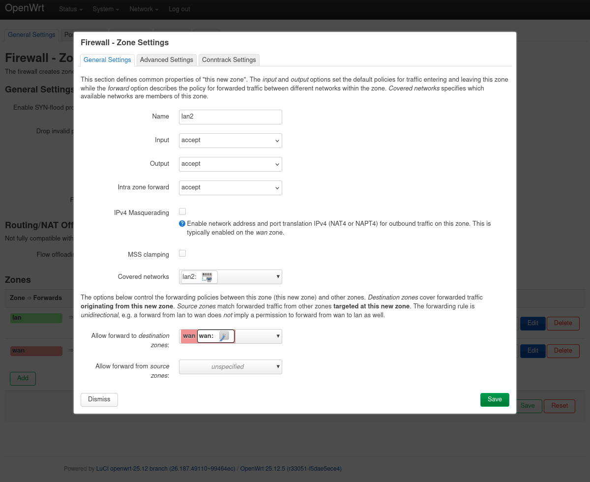
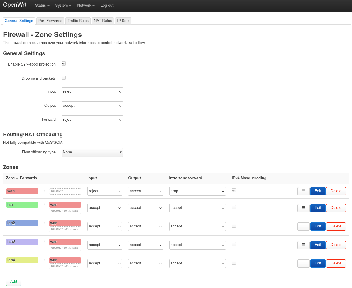
Firewall zones can be added directly in the interface dialog above or by Firewall → Zones → Add.
The existing lan zone can be basically copied and adapted for now – this will accept everything and allows WAN forwarding.
Managed Switch Setup
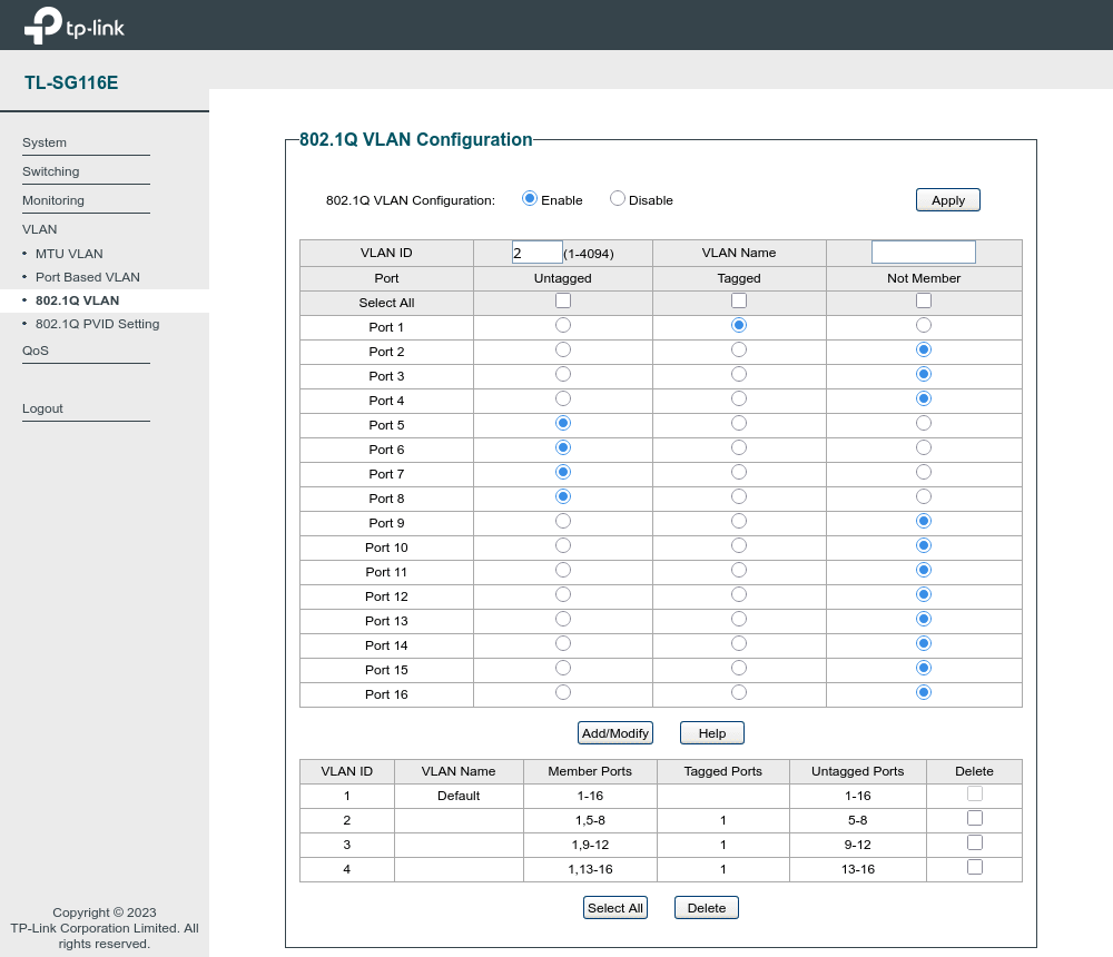
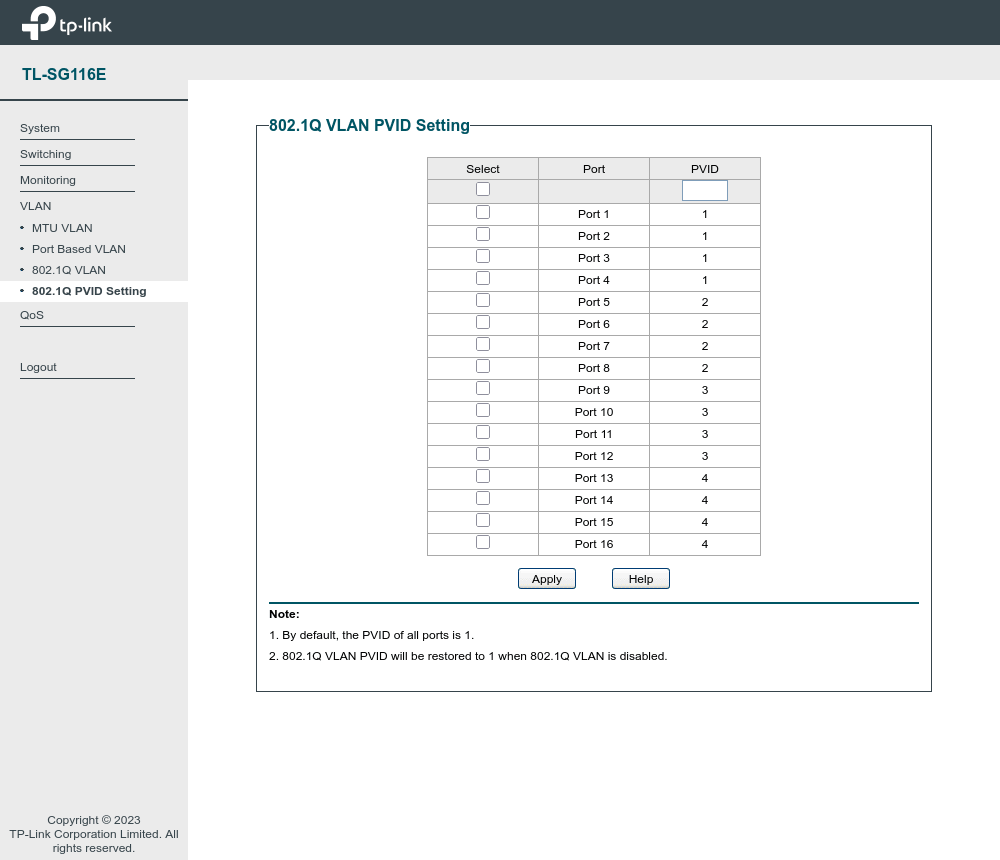
To make use of the default/untagged network and the three new tagged VLANs, a managed switch (e.g., a 16-port TP-Link) is to be connected and configured. After rewiring workstation and switch, the DHCP leases can be used for determining its management address.
- The uplink port (here: the first) should additionally participate in all tagged 802.1q VLANs.
- The other chosen ports should be assigned untagged for egress, and their PVID configured accordingly for ingress.
Test Connectivity
As functionality test, the workstation should be connected to one of the newly VLAN-enabled switch ports instead. If successful, DHCP should yield a 192.168.2.X address instead of the previous 192.168.1.X allocation – interwebs access via WAN forwarding should work, too. With this baseline established, further configuration such as for WiFi and firewalling can follow.